XHLUX
XHLUX
The board shows a long, continuous designer linear lighting bar—matte black, razor-thin, floating under a concrete slab. Everyone signs the designer linear fixture inspiration image. Three weeks later the shop drawing arrives with joints, a canopy, a driver box and shorter modules.
Nothing failed. A rendering shows design intent. A shop drawing shows how that intent will actually be built, powered, suspended and serviced.
This page explains why custom linear lighting design often shifts between concept and submittal—and what to check so the translation is planned, not fought on site. It is not a critique of designers, not How to Choose Modern Linear Lighting for Offices and Retail in 4 Steps, and not Linear LED Suspension: What to Check Before You Order once hang geometry is already fixed.
For mount-type context, see How to Choose Linear LED Lighting: Suspended, Surface, or Recessed?—then return here when the issue is rendering versus buildable documentation.
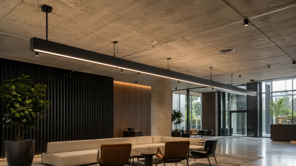
TL;DR: Renderings can skip extrusion limits, real hang points, drivers, feeds, joins and maintenance access. Shop drawings cannot. Expect engineering translation—not a mistake in the original concept.
Table of contents
- 🎨 1. Rendering intent versus buildable product
- 📏 2. Extrusion length limits and visible joins
- 🏗️ 3. Suspension points and structural reality
- 🔌 4. Drivers, canopies and power-feed positions
- 🔗 5. Continuous light, mechanical joints and electrical segmentation
- 🏢 6. Ceiling conditions that reshape the layout
- 🔧 7. Maintenance access that forces design changes
- 📋 8. What to align before the shop drawing is issued
- What to do next
- 🏁 Conclusion
- FAQ
🎨 1. Rendering intent versus buildable product
Architect-specified linear lighting on a rendering is a communication tool: proportion, rhythm, finish and mood. A shop drawing is a manufacturing and installation document: module lengths, join types, hang hardware, electrical entries and service clearances.
Design intent is not wrong. LED linear lighting in a project still has to pass through extrusion capacity, listing rules, site structure and maintenance policy. That gap is normal engineering translation—not “the designer missed something” by default.
Early linear lighting ideas in a package should be tagged as intent until a maker reviews extrusion, driver and hang feasibility.
🎯 Does a signed rendering guarantee a one-to-one shop drawing?
No. The shop drawing adds build, power, suspension and service facts the rendering was never required to show.
📏 2. Extrusion length limits and visible joins
A statement linear lighting run in a visualization can span the entire lobby in one glow. In production, aluminium extrusion, shipping, site access and joiner hardware often cap practical module lengths.
Shop drawings then show:
- Module breakdown and join locations
- End-cap types and cable entries
- Alignment tolerances at splices
A continuous look on screen does not prove a single extrusion can be fabricated, finished, shipped and installed as one piece. For join visibility and dark-seam risk, cross-check Stop Dark Seams Before You Join LED Linear Fixtures in related posts—mechanical joins are a separate approval from the rendering line.
🎯 Can every long rendering become one extrusion on site?
Not without product and logistics documentation that explicitly allows it.
🏗️ 3. Suspension points and structural reality
Linear pendant lights in renderings often float with evenly spaced, invisible hang points. Shop drawings must name:
- Permitted structural anchors or hang grids
- Cable length, swivel or gripper types
- Load paths and local code requirements
- Clearance to sprinklers, ducts or acoustic baffles
A hang point that looks elegant in a model may land on a void, a beam edge or a banned penetration zone on the issued ceiling plan. Moving a suspension point can affect visual symmetry and may require the fixture layout, feed position or module breakdown to be re-coordinated.
🎯 Can hang points stay exactly where the renderer placed them?
Only when structure, MEP and the hang system all agree at those coordinates.
🔌 4. Drivers, canopies and power-feed positions
Renderings frequently hide drivers, canopies and feed points inside ceiling voids or crop them out of frame. Shop drawings must place them somewhere physical:
- Integrated driver inside the housing
- Remote driver in an accessible enclosure
- Canopy size, feed entry and conductor count at the first module
On solid or tight ceilings, feed routing may follow the logic in How Do You Hide Wiring for Surface Mount Linear LED on a Solid Ceiling?—but the shop drawing still has to show the actual entry, not an implied void.
🎯 Can a shop drawing omit driver and feed locations if the rendering did?
No. Power and control paths must appear on the buildable document.
🔗 5. Continuous light, mechanical joints and electrical segmentation
Visually continuous light does not automatically mean one mechanical piece or one electrical feed. Shop drawings may show:
- First-module mains entry only
- Internal feed-through between sections
- Multiple drivers along a long run
- Control wiring passing through joins
A continuous luminous line on a rendering is an aesthetic goal. Electrical segmentation is a safety and product-design constraint. Treat “one glow” and “one feed for the entire run” as separate questions.
🎯 Does continuous appearance mean one power feed for the full run?
Not unless the electrical design and connector ratings explicitly allow it.
🏢 6. Ceiling conditions that reshape the layout
Real ceilings push back. Shop drawings respond to:
- Slab thickness, beams and bulkheads
- Sprinkler heads, diffusers and access panels
- Soffit steps and column wraps
- Required clearances to finishes or acoustic material
A bar length or drop height that fit the model may shorten, shift or break into segments when the reflected ceiling plan is issued. Proportions on the rendering were tuned to an ideal section; the shop drawing is tuned to the issued section.
🎯 Can shop drawings ignore MEP and structure if the rendering looked clean?
No. The shop drawing must coordinate the original visual proportions with the issued ceiling, structural and MEP constraints.
🔧 7. Maintenance access that forces design changes
Statement linear lighting shapes with tight cavities may trap drivers, connectors or LED modules. If service policy requires field replacement without destroying finish, the shop drawing may:
- Enlarge access zones or hinge sections
- Move drivers to reachable boxes
- Change join types to allow module swap
A concept image does not prove future maintenance is possible. Shop drawings exist partly so service teams can open, test and replace components.
🎯 Can maintenance be figured out after installation if the rendering looked fine?
Risky—access should be resolved on the shop drawing, not discovered on a lift after handover.
📋 8. What to align before the shop drawing is issued
| Topic | Rendering often shows | Shop drawing must show |
|---|---|---|
| Run length | One continuous glow | Module lengths, joins, shipping splits |
| Hang points | Ideal spacing | Structural anchors, loads, clearances |
| Power | Hidden or implied | Driver location, feed entry, conductor count |
| Electrics | Single uninterrupted line | Segments, feed-through, control paths |
| Ceiling | Clean plane | Clashes with MEP, structure, finishes |
| Service | Not shown | Access to drivers, modules, connectors |
Coordination checklist before you treat the rendering as final for production:
- Has the manufacturer reviewed the concept for extrusion and join limits?
- Are hang points on structure, not only on the 3D model grid?
- Where do driver, canopy and feed sit on the issued ceiling plan?
- Is electrical segmentation defined for the full run length?
- Do MEP and structure allow the shown drop and length?
- Can drivers and modules be serviced without destructive removal?
- Does the client understand which elements are intent versus buildable fact?
Rendering versus shop drawing at a glance
| Document | Primary job |
|---|---|
| Rendering / concept image | Sell proportion, finish and spatial rhythm |
| Shop drawing / submittal | Define buildable modules, hangs, power and access |
What to do next
- Send the concept image with ceiling plans, intended mount type and control method—not the PNG alone.
- Ask for a shop drawing that names joins, hang points, driver location and feed entry before finish sign-off.
- Run a short mock-up or sample module when the rendering shows a long, thin, continuous bar.
Translating custom linear lighting design from board to factory? Share the rendering, RCP, structure notes and target run lengths with XHLUX early—we can flag extrusion splits, hang conflicts and driver placement before the shop drawing surprises the project team.
🏁 Conclusion: Why do custom linear lighting designs change between rendering and shop drawing?
Because they answer different questions. The rendering carries design intent; the shop drawing carries build, power, suspension and service reality. Length limits, structure, drivers, feeds, joins and maintenance turn a beautiful line into a documented product. Plan that translation early and the changes read as engineering—not betrayal of the concept.
Explore our related blog posts:
- Linear LED Suspension: What to Check Before You Order
- Stop Dark Seams Before You Join LED Linear Fixtures
- How to Choose Modern Linear Lighting for Offices and Retail in 4 Steps
Technical Notes
- No universal maximum module length or extrusion size appears here—use the manufacturer submittal for the quoted SKU.
- Local structural, electrical and access rules remain project-specific.
- This page does not replace licensed engineering review of hang loads or power design.