XHLUX
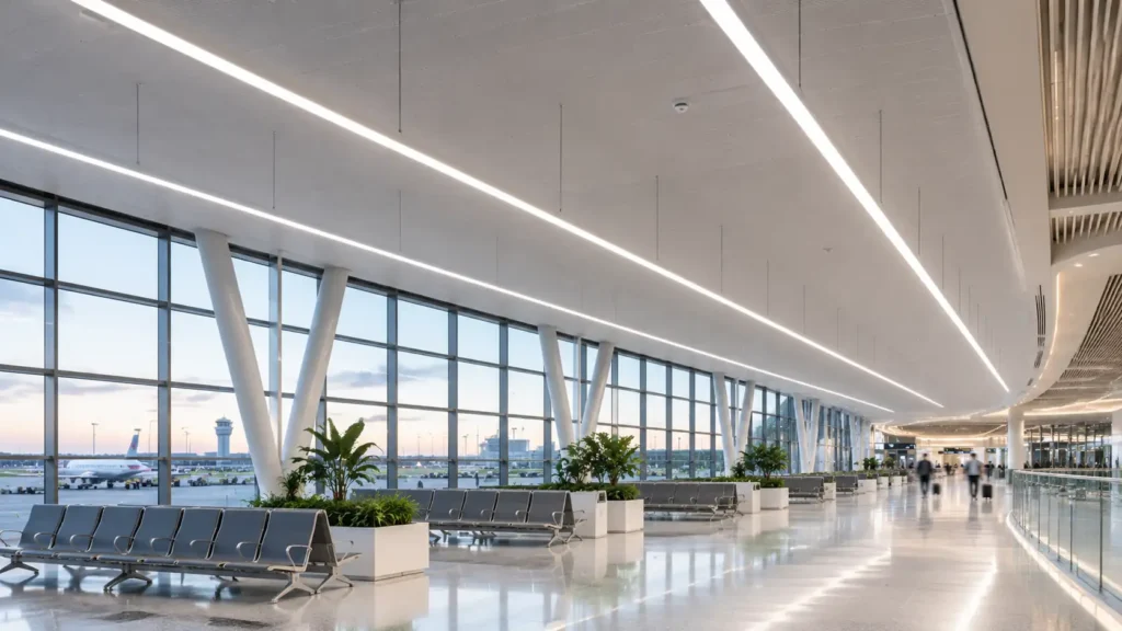
Continuous linear lighting is not the same as hanging several bars next to each other with separate feeds. In a true continuous-row arrangement, fixtures are designed to join end to end—mechanically and, when the product allows it, electrically—so the run reads as one line of continuous linear lighting rather than a set of isolated bars.
This guide covers continuous row LED lighting, LED linear lights continuous row builds, continuous row installation, LED linear fixture connection, and LED linear through-wiring. It separates two architectures that are often confused:
- Independent LED linear fixtures connected end to end.
- Pre-wired linear trunking with interchangeable lighting modules.
Never transfer run limits, connectors or feed rules from one architecture to the other.
TL;DR
- Confirm whether you are joining fixtures or building a trunking rail first.
- Use only that system’s mechanical joiners and electrical connectors.
- Through-wiring is not the same as feeding every fixture separately.
- Power-feed position and maximum run length come from that datasheet—not a generic rule.
- Check alignment and optics at joints so housing gaps and dark seams are not confused.
Table of contents
- 1. What Is Continuous Row LED Linear Lighting?
- 2. What Components Are Needed to Connect LED Linear Lights?
- 3. How Do You Join LED Linear Lights End to End?
- 4. How Does Through-Wiring Work in Continuous Row Lighting?
- 5. Where Should the Power Feed Be Located in a Continuous Linear Lighting System?
- 6. How Long Can a Continuous Row of LED Linear Lights Be?
- 7. What Is the Correct Installation Sequence for Continuous Row LED Linear Lighting?
- 8. Can Continuous Row LED Linear Lights Be Installed Around Corners?
- 9. How Do You Avoid Visible Gaps Between Connected LED Linear Lights?
- 10. Which Mounting Method Is Suitable for Continuous Row LED Linear Lights?
- 11. What Control and Emergency Lighting Options Are Available for Continuous Row Systems?
- 12. What Should You Confirm Before Specifying a Continuous Row LED Linear System?
1. What Is Continuous Row LED Linear Lighting?
1.1 How Continuous-Row Lighting Works
Multiple linear luminaires are connected end to end so housings and, where designed, conductors continue along one axis. The result is a continuous lighting arrangement rather than a set of visually separate bars.
That does not mean LED strip lighting inside an aluminium profile. This article addresses commercial linear luminaires and trunking systems with published joiners and wiring diagrams.
1.2 Continuous Row vs. Individually Installed Linear Fixtures
Individually installed fixtures each take their own power feed and sit as separate units. Continuous-row fixtures share a designed joining path so the row can be supported and wired as a connected assembly.
Appearance can look similar from the floor. Installation and electrical responsibility do not.
1.3 Continuous Row Fixtures vs. Pre-Wired Trunking Systems
| Architecture | What you join | Typical electrical idea |
|---|---|---|
| Independent continuous-row fixtures | Fixture housing to fixture housing | Through-wiring / feed into a designated fixture (e.g. Ledalite Vectra continuous-row sheet; Cree CS Series) |
| Pre-wired trunking | Trunking rail sections, then modules onto the rail | Power and often control live in the trunking (e.g. Zumtobel TECTON; Goodlight Unify) |
On a Ledalite ArcForm / PureFX / Vectra continuous-row installation sheet, fixtures are joined and serviced by one power feed, with thru-wiring and a driver in every fixture. On Zumtobel TECTON trunking, trunking sections click together first; luminaires attach to the rail afterward. Those are different jobs.
🎯 What is continuous row LED lighting?
It connects compatible linear fixtures end to end into one continuous arrangement using that system’s mechanical and electrical connection parts.
2. What Components Are Needed to Connect LED Linear Lights?
This section names parts only—not install torque sequences or circuit theory.
2.1 LED Linear Fixture Sections
Order the published lengths for that family (for example 4′ / 8′ on Cree CS14/CS18). Some systems distinguish starting, intermediate and end sections; others use repeating housings with different feed accessories.
Do not mix individual fixture housings with trunking rail segments from another brand.
2.2 Mechanical Joiners and Connection Plates
Joiners, brackets or plates hold housings in line. On Cree CS continuous-row steps, adjacent fixtures are attached with the supplied screws and nuts. Ledalite continuous-row instructions use a ½” nipple through knock-outs between fixtures (nipple and locknut by others on that sheet).
2.3 Electrical Connectors and Through-Wiring Components
Quick-wire plugs, knock-out pass-throughs or male/female AC and dimming connectors move power (and sometimes control) between fixtures. Connector families are system-specific.
2.4 Power Feeds, End Caps and Mounting Accessories
Power-feed kits, end caps, suspension cables, tong hangers, surface clips and recessed frames complete the row. Trunking systems add starter feeds, busbar terminators and node connectors that fixture-only lines may not offer.
🎯 What parts are needed to connect LED linear fixtures in a continuous row?
Typically compatible fixtures, mechanical joiners, electrical connectors, power-feed parts, mounting accessories and end caps—exact SKUs follow that system design.
3. How Do You Join LED Linear Lights End to End?
Mechanical joining only. Through-wiring is Section 4.
3.1 Aligning Adjacent Fixture Sections
Bring fixture ends to the designed connection face. Check that spines or end plates line up before fasteners go in.
3.2 Installing Mechanical Joiners
Fit the designated plates, brackets or screw sets. On Cree CS, attach fixtures with the provided screws and nuts before mating electrical plugs. Keep the row straight as each joint closes.
3.3 Securing Fixture Housings
Tighten only the fasteners the sheet names. Re-check that joined sections cannot open under their own weight before you release temporary supports.
3.4 Checking Gaps and Joint Alignment
Inspect for stepped heights and open housing gaps. Correct any mechanical misalignment before completing the surrounding ceiling finish, where applicable, or proceeding with commissioning.
🎯 How do you join LED linear lights end to end?
Align the housings, install that manufacturer’s mechanical joiners, and secure them per the sheet for that model.
4. How Does Through-Wiring Work in Continuous Row Lighting?
4.1 What Is Through-Wiring?
Through-wiring carries supply (and often dimming) conductors from one fixture into the next inside the continuous row. It differs from landing a separate branch circuit on every housing.
4.2 How Power Passes Between Fixtures
On the Ledalite Vectra continuous-row sheet, thru-wiring uses quick-wire connectors and knock-outs; the last fixture’s wiring is terminated, then the first fixture receives the power feed. Between fixtures, wires pass through the joint nipple and are connected to the colour code.
On the Cree CS Series installation instructions, after mechanical attachment, male/female AC connectors and dimming connectors are mated through the knockout path, with ferrite and lead placement as drawn.
4.3 Through-Wiring vs. Individual Power Connections
A single-feed continuous row uses through-wiring so one entry point can supply multiple housings—within that sheet’s limits. Separately powered fixtures each need their own feed, even if they sit in a visual line.
Some Ledalite standalone instructions state every fixture contains its own driver and receives a direct power feed—that is not the continuous-row wiring story on the continuous-row sheet.
4.4 Electrical Connection Requirements
Identify conductors correctly, use only compatible connectors, and follow local electrical codes. Fixed wiring and isolation belong with qualified personnel where required.
🎯 Can multiple LED linear fixtures share one power feed?
Yes, when that product’s continuous-row through-wiring and load limits support the configuration—confirm on that datasheet, not by habit.
5. Where Should the Power Feed Be Located in a Continuous Linear Lighting System?
5.1 Power Feed at the Beginning of a Row
Many independent-fixture continuous rows feed the first (starting) luminaire, then through-wire onward—matching the Vectra “power to the first fixture” pattern and Cree’s Power Feed with Cable Support on luminaire #1.
Coordinate the ceiling junction box with that start position.
5.2 Power Feed at Intermediate Positions
Some systems allow intermediate or mid-row feeds. Trunking platforms often tap power along the rail. Fixture-only lines may forbid mid feeds unless an accessory is listed.
5.3 Power Feed and Wiring Access
Plan junction-box location, flex or conduit entry, and later access for service. Do not bury feed compartments behind finishes the sheet expects to remain openable.
5.4 Planning Multiple Power Feed Points
Long projects may need separate electrical sections with additional feeds. Locate those breaks on the lighting and electrical drawings before housings go up.
🎯 Where should the power feed be installed in continuous row lighting?
Often at the start of the row; intermediate feeds only when that system supports them. Position follows fixture design and the electrical layout.
6. How Long Can a Continuous Row of LED Linear Lights Be?
There is no universal fixture count.
6.1 Maximum Connected Fixture Length
Read the published maximum run length or maximum connected sections for that family. Architecture matters: a Vectra continuous-row sheet and a TECTON trunking sheet do not share one metre rule.
6.2 Electrical Load and Power Feed Capacity
Sum connected wattage and compare it with circuit capacity and the feed accessory rating. Cree CS warns that maximum connected load with a single power supply shall not exceed the maximum ampacity of the #12 AWG THHN through-wire conductors.
Zumtobel’s TECTON trunking installation instructions plan loading at 4 A per circuit (80% of maximum rating) and a maximum 12 A total for each feed point—on that trunking system only.
Goodlight’s Unify continuous-row launch note publishes a 16 A / 3500 W serial-row figure on 220 V AC for that trunking family; treat it as Goodlight’s published claim for Unify, not a limit for Cree, Ledalite or TECTON.
6.3 Voltage Drop and Power Distribution
Long conductor paths increase voltage drop. Stay inside the manufacturer’s electrical limits rather than estimating from another catalogue.
6.4 When Are Additional Power Feeds or Separate Runs Required?
When the sheet’s length, current or wattage limit is reached, split the installation into separate electrical sections or add approved feeds. Follow that wiring diagram.
🎯 How many LED linear fixtures can be connected in one continuous row?
No universal number—quantity depends on model, load, feed capacity, electrical design and the maker’s maximum-run specification.
7. What Is the Correct Installation Sequence for Continuous Row LED Linear Lighting?
Workflow only—do not re-teach joining or wiring detail here.
7.1 Preparing the Site and Installation Layout
Confirm the approved layout, mark positions, check ceiling structure, and verify power-feed and cable access points before lifting fixtures.
7.2 Positioning and Supporting the First Fixture
Install the starting fixture and its required supports (for example Cree’s Power Feed with Cable Support plus a Cable Support on luminaire #1). Check position and stability.
7.3 Assembling the Row According to the System Instructions
Add intermediate and end sections according to the manufacturer’s specified assembly sequence. Some fixture systems require mechanical joining before electrical connections, while others integrate wiring during the joining process. For trunking systems, connect the trunking sections first, then install compatible lighting modules.
7.4 Completing the Installation and Pre-Commissioning Checks
Secure the full row, re-check alignment and fixings, confirm connections are closed, then hand over for qualified electrical testing and commissioning.
🎯 What is the correct installation sequence for continuous row LED linear lighting?
Prepare site and layout, support the first fixture, assemble following that manufacturer’s order, then complete checks before commissioning.
8. Can Continuous Row LED Linear Lights Be Installed Around Corners?
8.1 Corner Connections in Independent Linear Fixture Systems
Many straight end-to-end fixture families are limited to linear joints. Dedicated corner housings exist only when that range lists them. Do not invent L-joints from straight joiners.
8.2 L-Shaped, T-Shaped and X-Shaped Trunking Configurations
Pre-wired trunking systems often publish L, T and X node connectors. TECTON documentation describes L-, T-, X- and flexible connectors for branching layouts; Goodlight Unify lists L, T and X connectors for trunking frames. Those parts belong to trunking—not to every linear bar.
8.3 Connecting Different Row Sections
Where branching is supported, treat main and branch sections as documented assemblies. Align intersections before locking connectors.
8.4 Limitations of Corner Connections
Connector availability, feed-through rules and control zoning are product-specific. Independent fixture systems and trunking systems do not share a universal corner kit.
🎯 Can LED linear lights form L-shaped or T-shaped continuous rows?
Only when that architecture publishes dedicated corner or branch connectors—common on trunking; often limited on straight fixture-only lines.
9. How Do You Avoid Visible Gaps Between Connected LED Linear Lights?
9.1 Choosing Compatible Fixture Sections
Use matching housing dimensions, joiners and optics from one family. Look-alike bars from another series create steps and dark seams.
9.2 Aligning Fixture Housings
Accurate mechanical joins and consistent mounting height keep the metal line continuous. Misaligned spines read as gaps even when connectors are seated.
9.3 Preventing Dark Spots at Connections
Dark seams can come from LED board setbacks, diffuser breaks or intentional blank joints—not only from open metal. Approve a joined sample under the project dimming level. See also Stop Dark Seams Before You Join LED Linear Fixtures.
9.4 Maintaining Consistent Light Appearance
Match CCT, colour consistency and diffuser type across the modules that meet at each joint. Mixed bins or optics break the line optically.
🎯 Why do gaps or dark spots appear between connected LED linear fixtures?
From housing misalignment, incompatible optics, diffuser gaps, or LED position/output differences at the joint.
10. Which Mounting Method Is Suitable for Continuous Row LED Linear Lights?
10.1 Suspended Continuous Row Installation
Cable or rod suspensions must keep connection points supported. Cree CS continuous-row suspension uses a Power Feed with Cable Support on the first luminaire and Cable Supports thereafter, not exceeding 18″ from the end on that sheet.
10.2 Surface-Mounted Continuous Rows
Surface clips or metal tong hangers (where listed) fix the spine to the ceiling. Keep join planes flush along the run.
10.3 Recessed Continuous Row Installation
Recessed housings need openings and frames designed for continuous joining. Some variants cannot continuous-row at all—Ledalite notes the air-return recessed version cannot be installed in continuous rows.
10.4 How Mounting Design Affects Fixture Connections and Support
Support at joints, accessory compatibility and service access all change with mount type. Confirm mounting compatibility at every connection point. Different mounting methods should only be combined when the fixture design and installation instructions support the arrangement.
🎯 Can continuous row LED linear lighting be suspended, surface-mounted, or recessed?
Some systems support all three; others only one or two. Confirm accessories and structure for the selected fixture.
11. What Control and Emergency Lighting Options Are Available for Continuous Row Systems?
11.1 DALI and 0–10V Dimming Options
Independent continuous-row fixtures and pre-wired trunking do not share one control story. On Cree CS Series continuous-row steps, after the housings are attached, the male/female 0–10V through-wiring connectors are mated through the knockout path on that installation sheet—evidence for that fixture family’s 0–10V harness, not for every linear bar.
Trunking platforms publish control in the rail. Goodlight Unify lists DALI and 1–10V dimming (not 0–10V) in the pre-wired trunking base. Zumtobel TECTON integrates system-level control wiring in the trunking architecture—confirm the control option and conductor map on that TECTON documentation, and do not copy Unify’s 1–10V wording onto a Cree 0–10V harness.
11.2 Emergency Lighting Integration
The same Goodlight Unify product sheet states emergency lighting as an available trunking-base function alongside power and dimming. Zumtobel TECTON likewise treats emergency as a trunking-system configuration rather than a generic bolt-on for any linear fixture. Independent fixture rows use only the emergency battery packs or dedicated emergency luminaires listed for that luminaire family—do not assume a Unify or TECTON emergency module fits a Vectra or Cree CS housing.
11.3 Sensors and Lighting Controls
Unify product literature describes luminaires, controls and sensors within the pre-wired trunking rail; occupancy or daylight modules belong on that rail only when the Unify accessories list them. Independent fixture continuous rows usually need separate sensor accessories. Confirm whether sensor power and signalling ride the continuous-row conductors for the selected product.
11.4 Control Wiring and System Compatibility
Control conductors must match the connected sections. Do not assume a DALI trunking node works on an independent-fixture through-wire harness, and do not rewrite Goodlight’s 1–10V as 0–10V when quoting that system.
🎯 What control and emergency lighting options are available for continuous row systems?
Depending on the product: DALI, 0–10V or 1–10V dimming, emergency modules, occupancy and daylight controls—compatibility and wiring must match that system.
12. What Should You Confirm Before Specifying a Continuous Row LED Linear System?
12.1 Confirm the Total Row Length and Fixture Configuration
Lock total length, standard module sizes, straight vs corner/branch layout, and starting/intermediate/end sections where the catalogue uses them.
12.2 Confirm Compatible Mechanical and Electrical Components
Joiners, through-wiring connectors, power feeds and end caps must be the same system. For linkable product language, see How to Connect Linkable LED Linear Lights.
12.3 Confirm Mounting, Power and Control Requirements
Suspended, surface or recessed; feed locations; dimming and emergency options; matching mounting kits.
12.4 Confirm Documentation, Certifications and Spare Parts
Require drawings, wiring diagrams, installation instructions, market certifications, spare joiners/feeds and after-sales support before the PO.
🎯 What should buyers confirm before specifying a continuous row LED linear lighting system?
Row length and layout, compatible join/feed parts, mounting and power/control needs, plus documentation, certifications and spares.
Conclusion
Connecting LED linear lights into a continuous row is a system decision: independent fixtures with joiners and through-wiring are not the same as pre-wired trunking with click-in modules. Specifying continuous linear lighting means locking that architecture before you order joiners or feeds.
Specify the architecture first, then follow that manufacturer’s mechanical sequence, electrical diagram and run limits. Mixing connectors or copying another brand’s ampacity is how rows fail on site.
XHLUX supplies commercial LED linear lights and supports OEM/ODM continuous-row discussions when the project needs matched joiners and feeds. Contact us with your row drawings to confirm the configuration.
Explore our related blog posts:
- What Is Continuous Linear LED Lighting and How It Works
- Surface-Mounted Linear Lights for Ceilings Without Recessing
- Linear LED Suspension: What to Check Before You Order