XHLUX
XHLUX

A lighting specifier selects recessed LED downlights for a commercial office project, confirms the beam angle, CCT, and CRI — then the electrical contractor asks which dimming protocol the building management system expects. The choice is not trivial. It determines the control wiring topology, the per-fixture driver cost, the commissioning workflow, and whether the lighting system can report energy data back to the BMS three years later.
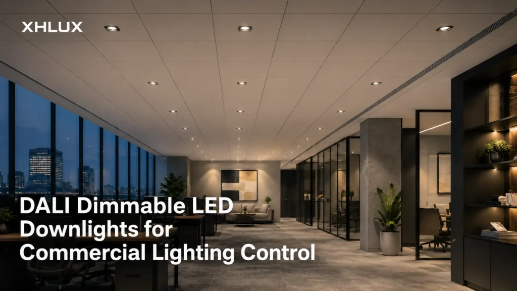
DALI (Digital Addressable Lighting Interface) is the most widely adopted open digital protocol for commercial lighting control. For projects where individual fixture addressing, bidirectional communication, and integration with building management systems are specification requirements, DALI is often the correct choice. This article explains what DALI means for commercial LED downlight specification — what the protocol does, how the bus wiring works, how driver selection affects capability, and what to confirm before ordering.
For broader commercial downlight selection guidance, see the Commercial LED Downlights Guide.
What DALI Is — and What It Is Not
DALI as an Open Digital Protocol (IEC 62386)
DALI is a dedicated lighting control protocol standardized under IEC 62386. Unlike proprietary control systems that lock a building owner into one manufacturer’s ecosystem, DALI is an open standard — control gear (drivers, ballasts, LED drivers) and control devices (sensors, switches, application controllers) from different manufacturers can interoperate on the same DALI bus, provided they comply with the relevant IEC 62386 parts.
The protocol uses a 2-wire bus that carries both data and can carry bus power. Communication is digital and bidirectional — the controller sends commands to individual fixtures, and fixtures can report status, energy consumption, and fault conditions back. This bidirectional capability distinguishes DALI from analog protocols such as 0-10V, where the controller can only send a dimming level with no feedback from the fixture.
DALI vs. DALI-2 — Key Differences for Specifiers
DALI-2 is the current version of the standard, introduced with IEC 62386 Parts 101, 102, and 103. The critical difference for specifiers is interoperability testing: DALI-2 certification requires products to pass conformance tests administered by the Digital Illumination Interface Alliance (DiiA), which was not mandatory under the original DALI standard.
For a commercial downlight specification, the practical question is: “Does this driver carry DALI-2 certification?” If the answer is yes, multi-vendor interoperability is guaranteed by the certification process. If the driver only states “DALI” without specifying DALI-2, it may still work on a DALI-2 bus (backward compatibility is generally maintained), but interoperability is not certified.
When writing a specification, request the driver’s DALI-2 certification documentation rather than accepting “DALI” as sufficient evidence of interoperability.
What DALI Is Not
DALI is often misunderstood. Three common misconceptions:
DALI is not a bus power system. The DALI bus can carry low-voltage power for bus communication, but the bus power supply (typically 16V DC, up to 250mA) is a separate component. Mains power to the LED driver and bus power for DALI communication are two distinct electrical systems. Specifying DALI does not eliminate the need for mains wiring to each downlight.
DALI is not plug-and-play. Unlike consumer wireless protocols, DALI requires commissioning — each control gear device must be assigned a short address, group memberships, and scene values before the system operates as designed. The commissioning step is not optional, and it requires a DALI commissioning tool or software.
DALI is not wireless. The DALI bus is a wired connection, typically using standard 2-core cable (1.5mm² is common for bus wiring alongside mains). Wireless lighting control protocols (ZigBee, BLE mesh, Casambi) are alternatives to DALI, not implementations of it.
Where DALI Fits in the Commercial Lighting Control Landscape
DALI occupies the middle layer of a commercial lighting control architecture:
– Field level: Individual LED drivers with DALI interfaces, DALI sensors, DALI switches – Bus level: The DALI bus connecting up to 64 control gear devices per line, powered by a DALI bus PSU – Gateway level: A DALI-to-BMS gateway (BACnet, KNX, Modbus) that exposes DALI bus data to the building management system – Management level: The BMS or lighting control software that provides scheduling, energy reporting, and user interface
For most commercial downlight projects, the key specification decisions happen at the field level (which driver) and the bus level (how many DALI lines, how many devices per line). The gateway and management levels are typically handled by the BMS contractor, but the downlight specifier must ensure compatibility between the selected drivers and the planned gateway protocol.
DALI Dimming for LED Downlights — How It Works
Digital vs. Analog Dimming — Why the Difference Matters
In an analog dimming system such as 0-10V, the controller sends a DC voltage (1V–10V) to the driver, and the driver interprets that voltage as a dimming percentage. The communication is one-way: the controller tells the driver what to do, but receives no confirmation and no status data back.
DALI dimming is digital. The controller sends a numerical command over the DALI bus to a specific address (or group, or broadcast), and the driver executes it. The driver can also respond — reporting its current dimming level, lamp hours, energy consumption, or a fault condition.
For commercial projects, the practical differences are:
| Feature | DALI | 0-10V |
|---|---|---|
| Communication direction | Bidirectional | Controller → Driver only |
| Addressing | Individual, group, broadcast | All fixtures on same control wire respond identically |
| Dimming range | Typically 0.1%–100% | Typically 1%–100% (driver-dependent) |
| Feedback | Lamp failure, energy data, hours run | None |
| Wiring | 2-wire bus (polarity-free) + mains | 2 control wires (polarity-sensitive) + mains |
| Commissioning | Required (addressing, groups, scenes) | None |
If the project requirement is only “the lights should dim from a wall switch,” 0-10V is likely sufficient and less expensive. If the requirement includes energy monitoring, fixture-level fault reporting, zoning that can be reconfigured without rewiring, or BMS integration, DALI is the appropriate protocol.
DALI Dimming Curves — Logarithmic vs. Linear
DALI defines a standard logarithmic dimming curve that maps the 254-step DALI level (0–254) to perceived brightness. The curve is logarithmic because human vision perceives brightness logarithmically — a DALI level of 126 produces approximately 10% of full light output, not 50%. This design ensures smooth, perceptually uniform dimming across the full range.
Some DALI drivers also support a linear dimming curve option. The logarithmic curve is the default and is correct for most commercial lighting applications because it matches human visual perception. Confirm the available dimming curve options with the driver specification if the project has specific dimming performance requirements.
Addressable Control — Individual, Group, and Broadcast Commands
DALI supports three addressing modes:
– Broadcast: A command sent to all devices on the bus simultaneously. All connected downlights respond together. Useful for simple on/off/dim control of an entire floor or zone. – Group: Devices can be assigned to up to 16 groups per DALI bus. A group command affects only devices in that group. Groups allow logical zoning (e.g., “window row,” “interior zone,” “conference room”) without physical control wiring changes. – Individual (Short Address): Each device on the DALI bus has a unique short address (0–63). Individual commands target one specific downlight. Useful for fine-tuning, maintenance, or energy monitoring at the fixture level.
The addressing structure enables a key DALI advantage: zones can be changed through software reconfiguration rather than physical rewiring. If an open-plan office is subdivided into smaller rooms, the DALI groups can be reassigned without touching a single control wire.
Bidirectional Communication — What the Fixture Reports Back
A DALI LED driver can report several data points back to the controller:
– Current dimming level – Lamp/lumen hours accumulated – Driver temperature (in some models) – LED module fault or open-circuit condition – Driver fault or power supply issue – Energy consumption data (in DALI-2 Part 102 compliant drivers)
For commercial projects with energy reporting requirements — increasingly common under building codes and sustainability certifications — the energy data capability of DALI-2 drivers is a specification advantage over analog protocols. Confirm whether the specified driver supports the DALI-2 energy reporting extensions (IEC 62386 Part 102) if energy monitoring is a project requirement.
DALI Bus Wiring and Topology for Downlight Installations
Bus Wiring Basics — 2-Wire Polarity-Free Topology
The DALI bus uses two wires that carry both data signals and bus power. The wiring is polarity-free — the installer does not need to observe positive and negative polarity, which reduces installation errors compared to polarity-sensitive analog control wiring.
Standard installation cable (1.5mm² 2-core, typically sheathed alongside mains wiring) is used for most commercial DALI bus installations. The bus wiring should be separated from mains wiring by the insulation rating of the cable sheath, but both can run in the same containment system if the cable is rated for the highest voltage present (typically mains voltage).
Line (Mains) vs. Bus Wiring Separation
Each DALI LED downlight requires two electrical connections:
1. Mains power: AC200-240V (or AC100-240V depending on region) to the driver input — this powers the LED module 2. DALI bus: 2-wire connection to the DALI bus — this carries control signals and bus power
These two circuits are electrically isolated within the driver. The mains wiring carries the load current for the LED (typically 250mA–600mA at DC36V after the driver), while the DALI bus carries only low-voltage communication signals and bus power (typically 16V DC, 2mA per device).
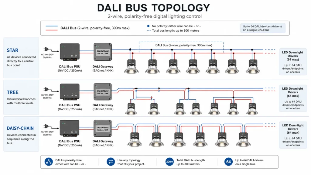
In a commercial ceiling layout, the mains wiring typically runs from the distribution board to each downlight position, while the DALI bus wiring connects all downlights in a daisy-chain, star, tree, or mixed topology. The two wiring systems should be documented separately on the electrical drawing set.
DALI Bus Power Supply Requirements
A DALI bus power supply (PSU) provides the bus voltage — typically 16V DC with a maximum current of 250mA. Each DALI control gear device (LED driver) draws approximately 2mA from the bus. At 64 devices × 2mA = 128mA, a single 250mA PSU can theoretically power a full DALI line. In practice, bus wiring resistance causes voltage drop over long runs, and the effective device count may be lower.
The bus PSU is a separate component — it is not integrated into the LED driver. For a project with 40 DALI downlights on one bus line, the specifier should confirm that the bus PSU current rating is sufficient for 40 devices × 2mA = 80mA, plus margin for bus wiring losses and any DALI sensors or switches on the same bus.
Topology Flexibility — Star, Tree, Daisy-Chain, and Mixed
DALI bus topology is one of the protocol’s practical advantages for commercial installation. Unlike DMX (which requires daisy-chain only) or some proprietary digital protocols, DALI supports free topology:
– Daisy-chain: Bus wire runs from fixture to fixture in sequence. Simplest to install and troubleshoot. Most common for open-plan office ceiling grids. – Star: All fixtures connect to a central junction point. Useful for zones that radiate from a central electrical closet. – Tree: Branches from a trunk line. Common in multi-room commercial floors where each room forms a branch. – Mixed: Any combination of the above.
The topology constraint is total bus length (typically 300m maximum at 1.5mm² cable cross-section, though this varies by installation conditions and device count) and total voltage drop, not the physical arrangement of connections.
Maximum Bus Length and Node Count
Standard DALI bus parameters:
| Parametro | Limit | Note |
|---|---|---|
| Control gear per bus | 64 devices | Drivers, relays, LED control gear |
| Control devices per bus | 64 devices | Sensors, switches, push-button interfaces |
| Bus PSU current | 250mA max | Sufficient for ~64 devices at 2mA each |
| Bus voltage | 12.0–22.4V DC (typical 16V) | Must remain above minimum at farthest device |
| Max bus length | 300m at 1.5mm² | Reduce for smaller cable cross-section |
| Max voltage drop | 2V | Measured from PSU to farthest device |
For projects exceeding 64 downlights on a single control zone, multiple DALI buses are required — each with its own PSU and gateway connection. This is a common scenario in large commercial floors and should be planned at the electrical design stage, not discovered during commissioning.
DALI Driver Selection for LED Downlights
Driver-Integrated DALI Interface — What to Confirm Per Model
The DALI interface is built into the LED driver, not the LED module. This means:
– The same LED downlight housing can be paired with different driver protocols by selecting a different driver at the specification stage – DALI capability is determined by the driver model, not by the downlight product series – A downlight specified with a TRIAC driver cannot be converted to DALI by changing a setting — the driver must be physically replaced
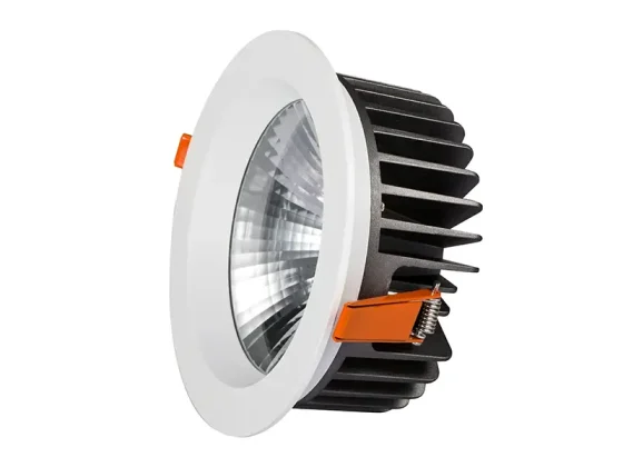
For XHLUX commercial LED downlights, DALI is available as a dimming protocol option depending on the driver selected. Driver brands compatible with DALI configuration include Tridonic, Philips, Osram, HEP, TCI, BOKE, and Lifud. The exact driver model, DALI interface version, and certification status should be confirmed per product code at the specification stage.
DALI Driver Current, Voltage, and Power Factor
For recessed LED downlights in the 10W–25W range, the LED driver converts mains voltage (AC200-240V or AC100-240V) to constant-current DC output (typically 250mA–600mA at DC36V, depending on wattage). The DALI interface is independent of the LED drive current — it handles only the control communication.
Power factor (PF) for commercial LED drivers with DALI interface should be above 0.9 at full load. Confirm the PF specification for the selected driver, particularly for projects subject to power quality requirements under local electrical codes.
Driver Brand Compatibility
Different driver manufacturers implement DALI interfaces with varying feature sets. When specifying DALI drivers for a project with multiple downlight types, using the same driver brand across all fixtures simplifies commissioning — the DALI addressing, dimming curve behavior, and fault reporting will be consistent.
For projects where the BMS integrator has a preferred driver brand or DALI gateway brand, confirm compatibility between the selected driver and gateway before ordering. While DALI is an open standard, implementation differences between manufacturers can affect advanced features such as energy reporting and luminaire data.
Isolated vs. Non-Isolated DALI Drivers
DALI drivers are available in isolated and non-isolated configurations. The isolation refers to electrical isolation between the DALI bus and the mains power circuit:
– Isolated DALI drivers: The DALI bus circuit is electrically isolated from the mains circuit. This provides protection against mains voltage faults reaching the DALI bus and is the recommended configuration for most commercial projects. – Non-isolated DALI drivers: The DALI bus shares a common reference with the mains circuit. This is less expensive but carries a risk: a mains fault on one driver can propagate to the entire DALI bus, potentially damaging all connected DALI devices.
For commercial projects, isolated DALI drivers are recommended unless the project’s electrical design specifically validates non-isolated operation and the cost difference is a material factor in the specification decision.
Commissioning, Addressing, and BMS Integration
DALI Addressing — Short Address, Group, and Scene Assignment
Commissioning is the process of assigning DALI addresses, groups, and scenes to each connected device. It is a mandatory step — a DALI bus with unaddressed devices will not respond to individual or group commands.
The commissioning workflow typically follows this sequence:
1. Device discovery: The commissioning tool scans the DALI bus and identifies all connected control gear by their random long address 2. Short address assignment: Each device is assigned a unique short address (0–63). This is the address used for individual control commands 3. Group assignment: Each device is assigned to one or more of the 16 available groups 4. Scene programming: For each group, up to 16 scenes can be programmed — each scene stores a dimming level for every device in that group 5. Verification: The commissioner tests each address, group, and scene to confirm correct assignment
Commissioning requires a DALI commissioning tool — either a handheld device or PC-based software connected to the DALI bus through a USB-to-DALI interface. The building’s electrical contractor or the BMS integrator typically performs commissioning, but the addressing schedule (which fixture gets which address) must be prepared by the lighting designer or electrical engineer before commissioning begins.
DALI Commissioning Tools and Software
Several DALI commissioning software platforms are available from different manufacturers. The commissioning tool must be compatible with the DALI gateway being installed — some gateways include built-in commissioning functions, while others require an external commissioning tool.
For projects using DALI-2 certified devices, the DALI-2 standard includes provisions for standardized commissioning procedures that reduce manufacturer-specific dependencies. Confirm with the gateway supplier whether their platform supports DALI-2 standardized commissioning.
DALI Gateway and BMS Integration
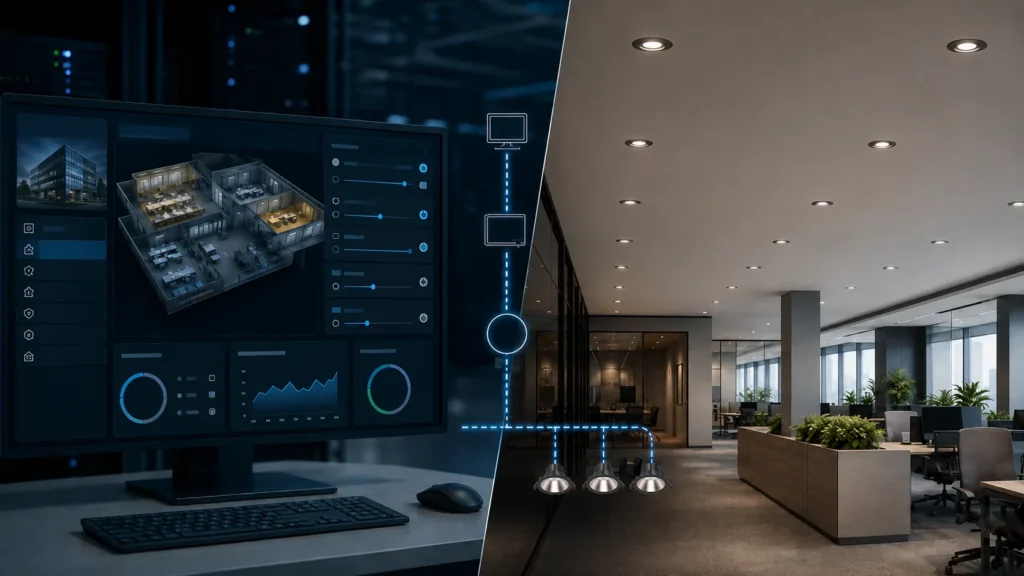
A DALI gateway bridges the DALI bus to the building management system. The gateway translates DALI commands and data to the BMS protocol — typically BACnet, KNX, or Modbus. Key gateway specification points:
– Number of DALI buses supported per gateway (typically 1–4) – BMS protocol supported (BACnet IP, BACnet MSTP, KNX TP, Modbus RTU, Modbus TCP) – Whether the gateway supports DALI-2 energy reporting data – Whether the gateway supports automatic address recovery after driver replacement
The gateway is the single point through which the BMS sees the entire lighting installation. If the gateway loses power or communication, the BMS loses visibility of all DALI bus data — though the DALI bus itself continues to operate and fixtures retain their last commanded state.
Re-Commissioning After Fixture Replacement
When a DALI LED driver fails and is replaced, the new driver arrives from the factory unaddressed — it has no short address, no group assignment, and no scene values. The DALI bus detects the new device, but until it is recommissioned, it will not respond to group or individual commands.
DALI-2 application controllers with automatic address recovery can detect the replacement and reapply the previous address and scene settings automatically — but this capability is not universal. If the project’s DALI gateway does not support automatic recovery, a manual recommissioning visit is required each time a driver is replaced.
For commercial projects where maintenance access is expensive (high ceilings, occupied spaces, cleanroom environments), automatic address recovery should be specified as a gateway requirement.
DALI vs. Alternative Dimming Protocols for Commercial Downlights
DALI vs. 0-10V — When Analog Is Sufficient
0-10V analog dimming is simpler and less expensive than DALI. It is the right choice when:
– The project requires only group-level dimming (all fixtures on the same control wire respond together) – No energy monitoring or fixture-level feedback is required – The BMS integration is minimal or non-existent – The project budget does not support DALI commissioning
DALI is the right choice when any of the following apply:
– Individual fixture addressing is required – Zones may need to be reconfigured after initial installation – Energy monitoring and reporting are specification requirements – Bidirectional communication with the BMS is needed – The project scope exceeds approximately 30–50 fixtures (at which point DALI commissioning cost is amortized across the larger device count)
DALI vs. TRIAC Phase-Cut — Retrofit vs. New Construction
TRIAC (phase-cut) dimming uses the existing mains wiring to carry a modified AC waveform that the driver interprets as a dimming level. It is the standard retrofit solution — no control wiring is needed, and existing wall dimmers can often be reused.
TRIAC is appropriate for:
– Retrofit projects where running new DALI bus wiring is impractical – Small commercial spaces (under 10–15 fixtures) where DALI commissioning overhead is disproportionate – Projects with simple dimming requirements and no BMS integration
TRIAC is not appropriate for:
– New commercial construction where control wiring can be included in the initial electrical installation – Projects requiring fixture-level energy monitoring or fault reporting – Large-scale projects where phase-cut dimming across many fixtures causes power quality issues (harmonic distortion, flicker at low dimming levels)
DALI vs. Wireless Protocols — Reliability and Scalability
Wireless lighting control protocols (ZigBee, BLE mesh, Casambi) eliminate control wiring — each fixture communicates wirelessly with a gateway or mesh network. This is attractive for retrofit projects and for spaces where physical control wiring is difficult to install.
However, wireless protocols carry trade-offs that specifiers should evaluate:
– Reliability: Wireless networks are subject to interference, range limitations, and packet loss. In high-density commercial ceilings with metal fixtures, ductwork, and shielding materials, wireless signal propagation can be unpredictable. DALI wired bus communication does not have these vulnerabilities. – Scalability: Wireless mesh networks can scale to hundreds of devices, but network performance degrades as the mesh depth increases. DALI’s wired bus has deterministic performance regardless of device count (within the 64-device limit per bus). – Power: Wireless fixtures require the driver to be powered for the wireless module to operate — meaning the mains must be energized even when the lights are “off.” This is important for energy calculations and standby power budgets. – Longevity: Wireless protocol standards evolve rapidly. A DALI wired bus installed today will still be serviceable and compatible with new control gear in 15 years, which is a meaningful consideration for commercial buildings with long maintenance cycles.
Mixed-Protocol Projects
It is common for large commercial projects to use multiple protocols in different areas:
– DALI for open-plan office floors requiring BMS integration and energy reporting – 0-10V for back-of-house, storage, and utility areas – TRIAC for small meeting rooms and retrofit sections – Wireless for heritage buildings or architectural spaces where new control wiring is not permitted
A DALI gateway with multi-protocol support can unify these zones under a single BMS interface, presenting DALI, 0-10V, and wireless zones through a consistent BACnet or KNX data model. When specifying a mixed-protocol project, confirm that the selected gateway supports all protocols present.
Specifying DALI LED Downlights — Pre-Order Checklist
Protocol Confirmation
– [ ] Confirm DALI or DALI-2 interface per driver model number – [ ] Request DALI-2 certification documentation if interoperability claims are required – [ ] Confirm dimming range (0.1%–100% typical; verify minimum level per driver) – [ ] Confirm dimming curve type (logarithmic default; linear if required) – [ ] Verify driver supports required DALI command set (basic dimming vs. extended commands for energy data)
Electrical Documentation
– [ ] Prepare DALI bus topology diagram showing all device connections and cable routing – [ ] Calculate DALI bus PSU sizing: N devices × 2mA + margin ≤ 250mA per bus – [ ] Verify total bus length ≤ 300m at selected cable cross-section – [ ] Confirm bus voltage drop from PSU to farthest device ≤ 2V – [ ] Confirm mains voltage per fixture (AC200-240V or AC100-240V as applicable) – [ ] Verify driver power factor ≥ 0.9 at full load – [ ] Confirm isolated DALI interface unless non-isolated is specifically validated
Commissioning Plan
– [ ] Prepare DALI short address schedule — fixture location → short address mapping – [ ] Define group assignments — up to 16 groups per bus – [ ] Define scene values per group — up to 16 scenes per group – [ ] Confirm commissioning tool compatibility with selected DALI gateway – [ ] Verify gateway supports automatic address recovery if required – [ ] Schedule commissioning visit after all fixtures are installed and mains is energized
Certification and Compliance
– [ ] Confirm DALI-2 certification status per driver and gateway model – [ ] Request relevant compliance documentation for target market (CE, ENEC, CB, RoHS, EMC) – [ ] Confirm gateway protocol compatibility with BMS (BACnet IP/MSTP, KNX TP, Modbus RTU/TCP) – [ ] Verify driver conforms to relevant IEC 62386 parts for required features
FAQ
Conclusion
DALI is the most widely adopted open digital protocol for commercial lighting control, and for good reason: it provides addressable, bidirectional, and topology-flexible dimming that integrates with building management systems through standardized gateways. For commercial LED downlight projects where individual fixture control, energy monitoring, or BMS integration is specified, DALI is the appropriate protocol choice.
However, “DALI” on a specification sheet is a starting point, not a completed specification. The bus topology, PSU sizing, driver certification status, commissioning plan, and gateway compatibility all need to be confirmed before ordering. The pre-order DALI checklist in this article provides the verification framework — the product specification sheet for the selected driver provides the data to complete it.
For current XHLUX LED downlight models with DALI dimming configuration options, visit the XHLUX LED Downlight product category. For broader commercial downlight selection guidance, see the Commercial LED Downlights Guide.