XHLUX
XHLUX


At a Glance
- Installing track lighting in a drop ceiling (suspended ceiling) is mechanically different from installing it on plasterboard or concrete. The ceiling is a grid of lightweight T-bars supporting acoustic tiles — the track must be mounted to the grid structure, not to the tiles themselves.
- The single most common installation mistake is attaching track directly to ceiling tiles. Ceiling tiles are not load-bearing — they crack under the weight of a track rail plus fixtures. The track must be anchored to the T-bar grid using grid-compatible clips or brackets.
- Drop ceiling installations also require planning for the power feed. The mains connection must reach the track through the ceiling void — if the junction box is above the ceiling, a flexible conduit or cable drop through a tile penetration is needed. If no junction box is available above the ceiling, a surface-mounted conduit from a wall outlet may be required.
Mounting Methods for Drop Ceilings
Surface-Mount on the Grid
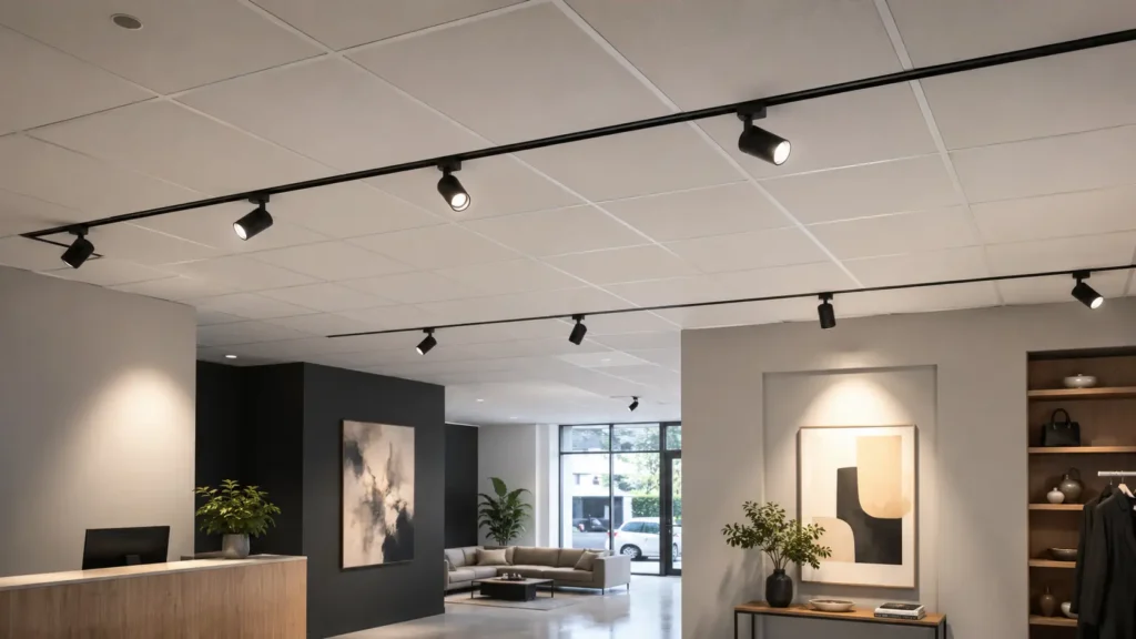
The most common method: the track is mounted directly on top of the ceiling T-bars, running parallel or perpendicular to the grid lines. The track sits on top of the T-bar flanges and is secured with grid clips that grip the T-bar from below.
When to use: the ceiling grid is exposed (no tiles), or the track is intended to sit flush with the tile surface. This method keeps the track visible on the ceiling plane — the track body sits approximately 5–10mm below the tile surface.
What to check:
– Grid clip compatibility with the specific T-bar profile (15/16″ and 9/16″ are the standard commercial sizes)
– Track weight plus fixture weight distributed across multiple T-bar support points
– Access above the ceiling for the power feed connection
Suspended Below the Grid
The track hangs from the structural ceiling above on threaded rods or cable suspenders, passing through the ceiling tile plane. The track floats below the tile surface, typically 150–500mm below.
When to use: the ceiling is high (above 3 metres) and the track needs to be closer to the target surface; the track is meant to be a visible architectural element; or the ceiling void contains obstructions that prevent surface-mounting.
What to check:
– Rod or cable mounting points must be anchored to the structural ceiling, not to the T-bar grid
– The tile around each rod penetration needs a trim ring or grommet
– The power feed cable runs along the rod or inside a conduit sleeve
Recessed into the Grid
The track sits within the ceiling grid, replacing one row of ceiling tiles, so the track face is flush with the surrounding tile surface. Only the fixture heads protrude below the ceiling plane.
When to use: architectural interiors where the track should be concealed; high-end retail and gallery spaces where only the light — not the track — should be visible.
What to check:
– The track extrusion must be the same width as the ceiling grid opening (typically 24″ or 600mm modular)
– Additional support brackets are needed to carry the track weight — the adjacent T-bars alone are insufficient
– Future fixture additions are more difficult because the track is recessed — the fixture heads must be installed from below with limited clearance
Weight and Load Distribution
A 2-metre aluminium track section weighs approximately 1–2 kg. With 4–6 fixture heads at 200–400 grams each, the total load per 2-metre run is approximately 2–4.5 kg. This is well within the load capacity of a standard T-bar grid (typically rated for 7–15 kg per support point, depending on the grid specification and suspension wire spacing).
The critical point is not the total weight but the distribution. Track weight concentrated on a single T-bar without additional support can deflect the bar and crack the adjacent ceiling tiles. Distribute the load across multiple support points using grid clips spaced every 600–900mm along the track.
For suspended track installations, the threaded rods or cable suspenders carry the track load independently of the ceiling grid. The ceiling tiles are not load-bearing in this configuration — the track is supported entirely by the structural ceiling above.
Power Feed: Access Above the Ceiling
The power feed is the electrical connection between the building’s mains supply and the track. In a drop ceiling installation, the junction box is typically located above the ceiling in the ceiling void. A flexible conduit or cable runs from the junction box, through a penetration in a ceiling tile, to the track’s end-feed or centre-feed connector.
If there is no accessible junction box above the ceiling, the power must be brought to the track through a surface-mounted conduit running along the ceiling or wall from the nearest outlet. This is more visually intrusive but is the only option when the ceiling void is sealed, fire-rated, or contains asbestos-containing materials that cannot be disturbed.
The power feed connection to the mains supply must be performed by a licensed electrical contractor. The mechanical mounting of the track and fixtures is electrical work only if it involves connecting to the mains — attaching fixtures to an already-powered track does not require an electrician.
Ceiling Tile Modifications
Installing track lighting in a drop ceiling often requires modifying ceiling tiles — cutting holes for power feed cables, trimming tiles around suspended rod penetrations, or replacing a row of tiles with a recessed track section.
Key considerations:
- Fire-rated ceilings: if the ceiling forms part of a fire compartment, any penetration through the ceiling tiles or grid must be sealed with fire-rated materials to maintain the fire rating. This applies to power feed cable penetrations, suspended rod penetrations, and any gaps around recessed track sections.
- Tile replacement: standard acoustic ceiling tiles are inexpensive and easily replaced. If a tile is damaged during installation or if the layout changes later, replacement tiles are available from any building supply. Keep a few spare tiles from the original batch for colour matching.
- Asbestos: ceiling voids in buildings constructed before the 1980s may contain asbestos-containing materials. If the building age is uncertain, have the ceiling void surveyed before any work that disturbs the tiles or the grid. Disturbing asbestos-containing materials without proper containment is a serious health and regulatory risk.
Track Layout Patterns for Drop Ceilings
Drop ceiling grids provide a natural reference for track layout because the grid lines are already straight, parallel, and regularly spaced.
- Parallel to grid: the simplest layout. The track runs parallel to the main T-bar runners, either directly on top of a T-bar or suspended below it. This layout works well for corridors, aisles, and perimeter wall displays.
- Perpendicular to grid: the track crosses the T-bar runners at right angles. Each crossing point requires a grid clip or support bracket. This layout is common when the track needs to run perpendicular to the main ceiling grid direction.
- Diagonal: the track runs at an angle to the grid lines. This requires the most support hardware because the track crosses grid lines at irregular intervals, and each crossing point needs individual support. Diagonal layouts are used for aesthetic effect — the track becomes a visual feature against the orthogonal grid pattern.
- Grid replacement: one or more rows of ceiling tiles are replaced with track sections, so the track integrates into the grid as a continuous linear element. This is the most architecturally integrated approach but requires the track extrusion width to match the grid module.
Frequently Asked Questions
What to Do Next
Before purchasing track lighting for a drop ceiling installation, confirm the grid type (T-bar profile width), the mounting method (surface, suspended, or recessed), the power feed access (junction box above ceiling or surface conduit), and whether the ceiling is fire-rated or contains asbestos. These four factors determine the installation hardware, the electrical scope, and the regulatory requirements.
Data notes: Track weights, fixture weights, and T-bar load capacities are representative of standard commercial ceiling grid systems and aluminium track lighting products. Specific values vary by manufacturer and grid specification. Fire-rating requirements and asbestos regulations vary by jurisdiction and building age. Electrical installation must be performed by a licensed electrical contractor in accordance with local codes. Ceiling void surveys for asbestos should be conducted by a qualified asbestos surveyor.