XHLUX
XHLUX
A linear led uplight can send a continuous line of light upward and still produce a ceiling with bright bands, dark joints and interrupted reflections. The ceiling is part of the optical system, so its surface, geometry and obstructions matter as much as the luminaire label.
Use this page after deciding that indirect light is useful, but before approving the uplight ratio, suspension gap, row position or ceiling finish.
For the basic distinction between direct and indirect distributions, start here:
→ Oświetlenie liniowe bezpośrednie czy pośrednie: które sprawdzi się w Twoim projekcie?
For the broader suspension-height decision, use this guide:
→ Oświetlenie liniowe wiszące: jak nisko jest już za nisko?
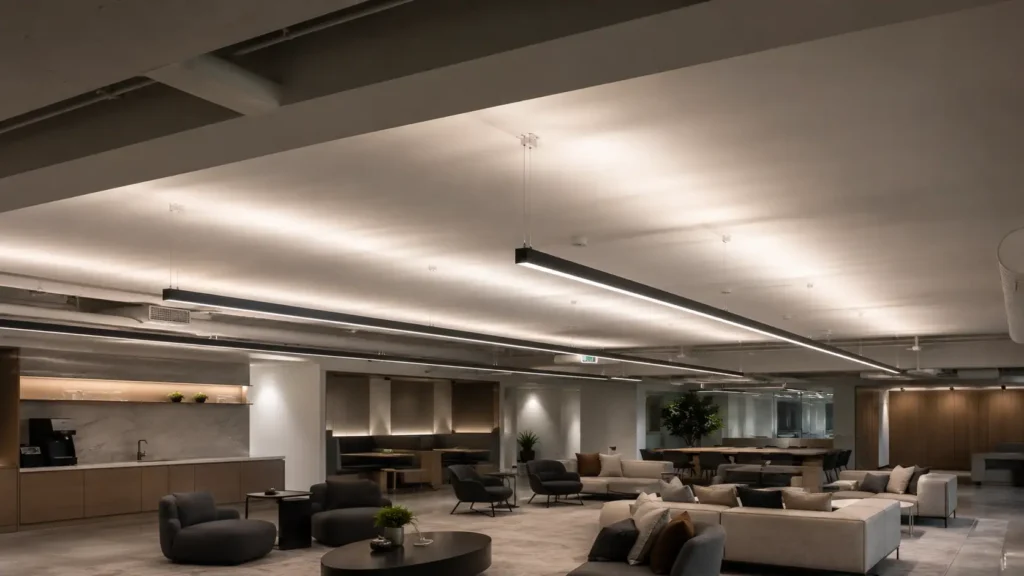
W skrócie: A continuous uplight source does not guarantee a continuous ceiling pattern. Check the ceiling reflectance, luminaire-to-ceiling distance, setback, uplight distribution, joints, obstructions and surface condition with the exact photometry and a representative mock-up.
1. Treat the ceiling as part of the luminaire
Indirect light reaches the room only after the ceiling receives and redirects it. That means a white-looking ceiling is not automatically an effective or uniform reflector.
Record the actual ceiling material, colour, gloss, texture and condition. Smooth painted plaster, mineral-fibre tile, perforated metal, timber slats and acoustic felt can return very different amounts and patterns of light. Dust, patch repairs and inconsistent paint batches may also become more obvious when illuminated at a shallow angle.
The reflected result depends on more than a single reflectance value. Specular or semi-gloss areas may show local highlights, while heavily textured or dark surfaces can reduce useful return. Perforations and open joints can interrupt the luminous field even when the average finish appears pale.
Dlatego architectural uplighting should be coordinated with the ceiling specification, not added after the reflected ceiling plan is complete. If the architect changes the finish or introduces rafts and exposed services, the lighting model and sample need another review.
🎯 Does a white ceiling guarantee even indirect light?
No. Reflectance, texture, gloss, joints, cleanliness and geometry all affect the visible result.
2. Give the uplight distribution enough room to develop
The gap between the luminaire and ceiling changes the size and intensity of the reflected pattern. Too little clearance can create a narrow bright stripe directly above the housing. More clearance may broaden the pattern, but it can also expose the suspension system or send light into nearby obstructions.
Do not specify one universal gap. Obtain the exact uplight intensity distribution for the selected length, output and optic, then test several heights. Review the ceiling luminance pattern as well as workplane illuminance.
The useful distance is measured from the uplight-emitting surface to the reflecting plane. A nominal suspension drop measured from structure may not describe that distance when the ceiling steps, slopes or includes rafts.
Dla linear LED uplight mounting, drawings should identify:
- Finished height of the uplight aperture
- Reflecting ceiling plane above each section
- Suspension and feed locations
- Distance to walls, beams, bulkheads and ceiling edges
- Any change in profile, optic or upward output along the row
The correct gap gives the distribution room to overlap without turning the ceiling into one intense line or a series of isolated patches.
🎯 Is a larger ceiling gap always more uniform?
No. The result depends on the optic, output, row spacing, ceiling surface and surrounding geometry.
3. Check setback from walls, edges and level changes
A row placed close to a wall may push part of its uplight onto the vertical surface. That can create a bright corner, a visible scallop or an asymmetric ceiling band. Moving the row inward changes both the reflected pattern and the light returned to the room.
Ceiling edges create similar problems. Bulkheads, coffers, steps and floating rafts can cut through the distribution. A row centred within the available ceiling bay may still be optically off-centre if one side is open and the other is bounded by a deep edge.
Draw sections in both directions. A cross-section may show a suitable gap while the longitudinal view reveals end walls, beams or changes in ceiling level. For joined rows, check what happens at every end, corner and transition, not only in the middle of a typical section.
W cove uplighting design, the cove lip, internal finish and source setback form a small optical system. Those principles can inform an exposed linear uplight, but this article does not turn a suspended luminaire into a generic strip-light cove detail. Use the photometry and installation limits of the actual product.
🎯 Can the row simply follow the centre of the ceiling bay?
Only if that position also produces the required reflected pattern after walls, edges and level changes are included.
4. Map every obstruction above and beside the row
Uplight can make ceiling services more visible while allowing those same services to cast shadows. Ducts, beams, sprinklers, cable trays, acoustic baffles, signs and suspension hardware may interrupt the reflected field.
The diagram shows why a continuous source can produce either a continuous reflection or a broken ceiling pattern.
Obtain the coordinated ceiling-services drawing rather than modelling an empty ceiling. Identify the dimensions and finishes of large objects because a pale acoustic raft may redirect some light while a dark duct can absorb it and cast a pronounced shadow.
Also check the luminaire’s own suspension cables, power cord and canopy. Hardware placed inside the upward distribution can create repeated shadows that become more visible along a long row.
🎯 Can coordination wait until after the lighting calculation?
No. The calculation must include the objects that can block, absorb or redirect the uplight.
5. Do not assume every joined section emits the same uplight
A continuous housing can conceal discontinuities. Drivers, connectors, emergency modules, end caps and mechanical joiners may occupy space that an LED board cannot. The visible ceiling can therefore show darker points at joints even when the downward diffuser appears continuous.
Confirm the luminous length of every module and the gap between adjacent upward-emitting sections. Ask whether corner pieces, blank modules, feeds and control sections provide uplight. A product family image may show one continuous profile without documenting its continuous optical output.
For long runs of pośrednie oświetlenie liniowe, freeze these items before approval:
- Exact module lengths and uplight board positions
- Output and optic for every straight, corner and transition section
- Dark length at feeds, joiners, end caps and emergency components
- Driver tolerances and dimming behaviour between sections
- CCT and colour-consistency tolerances across the complete batch
- Maximum permitted run and electrical-feed arrangement
At low dimming levels, small differences between drivers can make adjoining ceiling bands visibly unequal. Test the nominated controls with a representative multi-section assembly, not only one isolated luminaire.
🎯 Does a seamless housing prove seamless uplight?
No. Verify the luminous length, joint gaps, components and output of every section.
6. Balance uplight ratio with useful room light
An uplight percentage describes distribution, not success. A high upward ratio may brighten an efficient ceiling but waste energy against a dark or obstructed one. A low ratio may provide only a decorative ceiling trace rather than meaningful ambient contribution.
Review upward lumens and downward lumens separately. Then model the reflected contribution using the actual room surfaces. Do not compare two luminaires only by total output if their up/down splits differ.
Ceiling uniformity should not be improved by simply increasing output until the darkest area looks acceptable. That can make the bright band too intense, increase source visibility or produce excessive room light. Change the gap, optic, setback, row position or ceiling coordination before adding power.
Also review glare from the luminaire itself. CIE 117-1995 explains that discomfort glare depends on observer position and viewing direction, while CIE 232:2019 addresses non-uniform LED source luminance. An indirect component does not cancel the direct source seen below or across the room.
🎯 Is a higher uplight percentage automatically better?
No. It is useful only when the ceiling can receive and redistribute that light effectively.
7. Approve the ceiling pattern, not just the luminaire
ISO/CIE 8995-1:2025 frames indoor workplace lighting around both light quantity and quality. For an uplight proposal, the approval evidence should therefore include the appearance and contribution of the ceiling, not only a luminaire schedule.
Użyj tej sekwencji:
- Fix the actual ceiling material, colour, texture and reflectance assumption.
- Draw the luminaire, walls, edges, obstructions and reflecting planes in section.
- Model the exact uplight distribution, output, length and joints.
- Review ceiling luminance, workplane results, vertical light and normal sightlines.
- Test several gaps and setbacks instead of compensating with output alone.
- Build a representative joined sample with the nominated controls.
- Record the approved height, setback, up/down split, ceiling finish and coordination limits.
IEC 62722-1:2022 and IEC 62722-2-1:2023 provide luminaire-performance frameworks, but project approval still needs the exact configuration and installation context. A compliant luminaire cannot make an unsuitable ceiling detail uniform by itself.
The right solution is the one whose complete ceiling pattern remains deliberate after joints, services, finishes, controls and tolerances are included.
🎯 What should the mock-up prove?
It should prove ceiling uniformity, joint behaviour, glare, dimming consistency and the appearance of the actual reflecting surface.
Co robić dalej
- Use the direct-versus-indirect guide linked in the introduction to confirm that uplight belongs in the project strategy.
- Use the suspension-height guide linked there to establish the available gap and sightline limits.
- Request the exact IES or LDT file, module drawing, uplight ratio and joint details.
- Coordinate the real ceiling finish, services, edges and reflecting planes before final calculation.
- Ask XHLUX to review a representative joined sample and the intended ceiling detail before the linear uplight configuration is released.
Notatki i źródła
- ISO/CIE 8995-1:2025, Światło i oświetlenie, Oświetlenie miejsc pracy, Część 1: Oświetlenie wewnętrzne.
- CIE 117-1995, Dyskomfort spowodowany odblaskami w oświetleniu wewnętrznym.
- CIE 232:2019, Dyskomfort spowodowany olśnieniem pochodzącym od opraw oświetleniowych o nierównomiernej jasności źródła światła.
- IEC 62722-1:2022, Wydajność oprawy oświetleniowej, część 1: Wymagania ogólne.
- IEC 62722-2-1:2023, Wydajność oprawy oświetleniowej, Część 2-1: Wymagania szczegółowe, oprawy oświetleniowe LED.