XHLUX
XHLUX
A long luminous shape is easy to recognize, but shape alone does not prove that the product is a complete linear luminaire. The useful product is an optical, electrical and mechanical system whose parts have been designed, tested and documented to work together.
Use this page when a drawing, quotation or sample says “linear light” but does not yet show what sits behind the diffuser, how sections join, where heat goes or what happens when a driver fails.
For basic pendant forms and terminology, start here:
→ Czym jest komercyjne oświetlenie liniowe wiszące: przewodnik dla początkujących
Aby dokonać wyboru między światłem roboczym skierowanym w dół a światłem sufitowym skierowanym w górę, skorzystaj z tego porównania:
→ Oświetlenie liniowe bezpośrednie czy pośrednie: które sprawdzi się w Twoim projekcie?
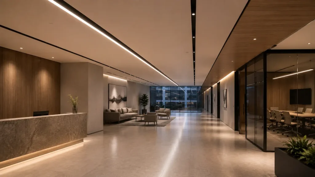
W skrócie: A long housing becomes a dependable luminaire only when its LED modules, optics, thermal path, driver, wiring, connectors, mounting parts and service plan work as one documented system. Approve the exact configuration, not a profile photograph or a generic wattage.
1. Define the complete product boundary
A luminaire is more than the light-emitting element. The approval boundary should include every part required to mount, power, control and maintain the installed product.
For a typical linear system, that means recording:
- Housing profile, end caps and diffuser or louvre
- LED boards or modules and their operating current
- Driver model, location and control interface
- Internal wiring, feed kit and protective-earth arrangement where applicable
- Joiners, suspension sets, brackets or recessed mounting frame
- Optical distribution and photometric file for the exact build
- Permitted lengths, finishes, ambient conditions and installation orientations
IEC 60598-1:2024 covers safety requirements for luminaires, including construction, marking and electrical matters. IEC 62722-1:2022 and IEC 62722-2-1:2023 address luminaire performance. These scopes reinforce a practical procurement point: a bare LED strip or isolated module is not evidence for the safety and performance of the completed assembly.
If a supplier changes the driver, board current, diffuser or joiner, the approved product boundary may have changed. The revised build needs its own evidence review rather than inheriting approval from a visually similar sample.
🎯 Is every long LED product a complete luminaire?
No. Confirm the housing, optics, driver, wiring, mounting parts and evidence as one defined assembly.
2. Read the light distribution, not the glowing line
An evenly glowing diffuser can hide very different distributions. One product may spread light broadly across a ceiling; another may concentrate it downward; a third may send separate direct and indirect components in controlled proportions.
Dobry linear LED luminaire design begins with the target and the photometric distribution. Ask for the IES or LDT file for the exact length, output, optic and diffuser. Then test the proposed spacing, mounting height, workplane illuminance, vertical light and glare in the project model.
A continuous appearance does not guarantee continuous performance. Bright bands can appear near board ends, connectors or feeds. Dark seams may become visible where housings join. At oblique viewing angles, the diffuser may reveal LED pitch that is invisible in a front-facing product photograph.
The drawing below separates the visual line from the system layers that create it.
🎯 Does a continuous glow prove uniform distribution?
No. Verify the exact photometric file and inspect board ends, joiners, feeds and oblique views.
3. Treat the housing as structure and heat path
The profile is not merely decorative. It holds the boards and optics in alignment, protects wiring, receives mounting hardware and carries heat away from temperature-sensitive components.
Review the section drawing rather than accepting an outside width and height. Check wall thickness, straightness, torsional stiffness, diffuser retention and the space available for wiring and connectors. Long runs amplify small tolerances: a slight twist or inconsistent extrusion can turn into a visible wave across a ceiling.
Thermal evidence must match the proposed configuration. Board current, LED density, ambient temperature, driver location, insulation conditions and mounting orientation all influence operating temperature. A longer housing provides more surface area, but it may also contain more LEDs and higher total power. Length alone does not prove cooler operation.
Dla suspended linear luminaire, the cable spacing and attachment details must keep the profile level without relying on the electrical cord as a structural suspension. For surface and recessed versions, confirm substrate, bracket intervals, access and any required clearances.
🎯 Is the aluminium profile only a visual finish?
No. It also supports alignment, mounting, diffuser retention, wiring protection and thermal transfer.
4. Verify drivers, feeds and control behaviour
Two visually identical runs can behave differently because their drivers and internal circuits differ. Record the exact driver manufacturer, model, current range, output limits, dimming method, minimum dim level and location.
Long or joined runs require a real electrical diagram. It should show:
- Feed positions and the maximum permitted load per feed
- Driver quantity and which sections each driver supplies
- Series or parallel arrangements inside the approved product design
- Cable sizes, connector ratings and protective-earth continuity where required
- DALI, 0-10 V, phase-cut or other control wiring
- Emergency modules, sensors and separate control zones
Do not assume one long luminous line behaves as one control address. A continuous run may contain several drivers, separate circuits or independently controlled zones. Conversely, multiple visible sections may be supplied by one remote driver if the manufacturer permits that exact arrangement.
Approve low-end behaviour with the nominated control. Check for flicker, shimmer, step changes, delayed starting, audible noise and different dimming levels between adjoining sections. A clean line at full output can become visibly segmented when dimmed.
🎯 Does one luminous run always mean one driver?
No. The run may contain several drivers, feeds or control zones, so approve the actual wiring diagram.
5. Design joins as optical and mechanical interfaces
The joiner has three jobs: align housings, maintain electrical continuity where applicable and keep the luminous line visually credible. Passing only one of those tests is insufficient.
Ask how straight sections, corners, crosses and branches are formed. Confirm whether each fitting is illuminated, partly illuminated or intentionally dark. A catalogue plan view can hide a shadow at the connector, a diffuser gap or a larger corner module.
Tolerance stacks matter in architectural linear lighting because the eye follows the line. Check extrusion cuts, diffuser lengths, end-cap thickness and connector play across the complete scheduled run. Dry-assemble a representative multi-section sample when the project depends on precise alignment.
Also establish where expansion, access or disassembly is allowed. A continuous-looking installation that cannot be opened without damaging the ceiling creates a maintenance problem even when its first-day appearance is excellent.
🎯 Is an electrical joiner enough for a seamless run?
No. It must also preserve housing alignment, diffuser continuity and the intended light distribution.
6. Separate LED maintenance from system life
A source-level lumen-maintenance projection is not a complete product-life claim. Drivers, connectors, optical materials, solder joints, control components and thermal interfaces can fail or drift before the LED package reaches its projected maintenance point.
The Illuminating Engineering Society’s PS-10-18 states that it is inaccurate to claim an entire luminaire lifetime from TM-21 projections alone because that method applies to LED components. Current ANSI/IES LM-80-21 and TM-21-21 remain useful for source maintenance, but the whole product needs a broader reliability and service review.
Before accepting a linear luminaire lifespan statement, request:
- The metric used, such as lumen maintenance, survival or a warranty period
- Test duration, operating current and relevant temperature conditions
- Driver-life information at the expected operating temperature
- Colour-maintenance evidence where visual continuity matters
- Replaceable, serviceable and non-serviceable component classification
- Spare-part policy for drivers, boards, diffusers, end caps and joiners
IEC 60598-1:2024 includes requirements and information around serviceable and non-serviceable components. Translate that product classification into a project plan: who can access the part, what must be removed and whether a replacement will still match the adjacent line.
🎯 Does an L70 projection equal luminaire life?
No. It addresses source maintenance, while drivers, optics, connectors and other parts have separate risks.
7. Approve evidence for the exact scheduled build
The final submittal should identify one build, not a family name with selectable options left unresolved. Length, output, CCT, colour quality, optic, diffuser, driver, dimming, mounting and finish should all match the schedule and sample.
Use this release sequence:
- Freeze the target tasks, mounting method and run geometry.
- Record every section, corner, joiner, feed, driver and suspension or bracket.
- Check photometry for the exact output and optic.
- Review safety, performance and control evidence for the finished assembly.
- Test a representative joined sample at full output and low dimming levels.
- Confirm access, component replacement and spare-part availability.
- Release the purchase order only after drawings, schedule, sample and evidence agree.
A family may share a profile while offering several board powers, drivers and optics. Do not let one favourable test report or one attractive sample silently cover variants it did not represent.
🎯 What should the purchase order identify?
The exact length, output, optic, driver, control, mounting, finish, joiners and service arrangement.
Często zadawane pytania
Co robić dalej
- Use the beginner guide linked in the introduction if the basic pendant forms and terms are still unclear.
- Use the direct-versus-indirect comparison linked in the introduction before fixing the optical distribution.
- Build one configuration schedule that fixes the profile, boards, optic, driver, control, joins and mounting parts.
- Request a joined sample and test it from normal viewing directions, at full output and at the specified minimum dim level.
- Ask XHLUX to review the exact schedule, drawings and service requirements before an OEM or project-based linear luminaire is approved.
Notatki i źródła
- IEC 60598-1:2024, Oprawy oświetleniowe, część 1: Wymagania ogólne i badania.
- IEC 62722-1:2022, Wydajność oprawy oświetleniowej, część 1: Wymagania ogólne.
- IEC 62722-2-1:2023, Wydajność oprawy oświetleniowej, Część 2-1: Wymagania szczegółowe, oprawy oświetleniowe LED.
- IEC 62717:2014 with Amendments 1:2015 and 2:2019, LED modules for general lighting, Performance requirements.
- Illuminating Engineering Society, PS-10-18, IES Position on LED Product Lifetime Prediction.
- ANSI/IES LM-80-21, Measuring Maintenance of Light Output Characteristics of Solid-State Light Sources.
- ANSI/IES TM-21-21, Projecting Long-Term Luminous, Photon, and Radiant Flux Maintenance of LED Light Sources.
- CIE 232:2019, Dyskomfort spowodowany olśnieniem pochodzącym od opraw oświetleniowych o nierównomiernej jasności źródła światła.