XHLUX
XHLUX
The reflected ceiling plan shows one straight line across a long, narrow zone—maybe a thirty-metre corridor wing or a bar-shaped office strip. The specifier stares at the axis and asks the question that stalls the layout: can this be one continuous ceiling run, or does it have to break somewhere?
That break point is an install and uniformity decision—not a guess from a clean line on CAD.
Ceiling linear lights on a single run only work when spacing, join limits, beam behaviour and mounting all still hold at the far end of the axis. This page answers where that line gets too long for one continuous piece—not which SKU wins on price.
This page answers whether one continuous ceiling linear run can go the full length of a long, narrow space, or where it should break. It does not cover module cost and supply-chain tradeoffs, covered in One Module or Many? A Long Linear Light Fixture Guide for Extended Runs. It is not the corridor-specific five-check formula in Ceiling-Mounted Linear Fixtures for Hallways: 5 Checks. It is not a general ceiling luminaire selection guide—see How to Choose Linear LED Luminaires for Office and Retail Ceilings for that path.
For the wider suspend / surface / recess map, start with كيفية اختيار إضاءة LED الخطية: معلقة، سطحية، أم غائرة؟—then return here for run-length limits on the ceiling plane.
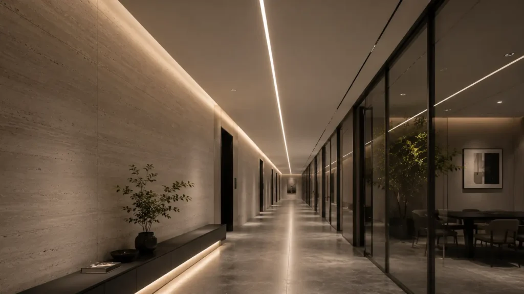
باختصار شديد: A ceiling linear run is too long when fixture spacing no longer reads even, when the maker’s single-piece or join span is exceeded, when beam output looks uneven along the axis, or when the narrow ceiling cannot support the mount you chose for that length. There is no universal metre cap—use the four checks below and the family datasheet.
جدول المحتويات
- 📏 1. Set fixture spacing before you judge run length
- 🔗 2. Know where a continuous run actually breaks down
- 💡 3. Watch for beam uniformity loss over distance
- 🛠️ 4. Match mounting to the space’s width and length
- ✅ Run length at a glance
- ما الخطوة التالية؟
- 🏁 Conclusion
- ملاحظات ومصادر
- التعليمات
📏 1. Set fixture spacing before you judge run length
Linear ceiling fixture spacing is a layout rhythm decision. Run length is a ship-and-install decision. Mixing them up is how a “short” run still looks broken.
On a long, narrow ceiling you may have either:
- One continuous luminous bar (one SKU line on the schedule), or
- Several discrete ceiling linear fixtures spaced along the same axis
Spacing answers how far apart separate heads or segments sit so the floor and walls look evenly lit. Run length answers how long one shipped piece or one joined chain can be before the maker, structure or driver says stop.
If spacing is wrong, a run that is technically “short enough” still reads as dark gaps and hot spots. Fix spacing on a mock-up bay or spacing guide first—then ask whether the continuous bar itself can span the full axis.
For a standard hallway with a published spacing starter, use the corridor five-check article linked in the boundary—not a spacing formula re-derived here.
🎯 Can one continuous bar ignore spacing rules?
No. A single bar still has optic throw and edge falloff; discrete multiples still need centre-to-centre spacing on the drawing.
🔗 2. Know where a continuous run actually breaks down
Continuous linear ceiling runs hit real limits in the catalogue and on the lift path—not on the specifier’s wish for one unbroken line.
A run is too long for one piece when any of these fail:
- Shipped length: the series’ longest single module is shorter than the axis total
- Unsupported span: published max span for your mount tier and output needs mid-run support you cannot add in a narrow void
- Join count: each join adds alignment and feed tolerance; stacked joins on a very long axis magnify small errors into visible steps or gaps
- Access: lift path, turning radius or a walled far end forces staged modules even when the drawing shows one line
- Feed splits: driver or circuit limits may require a planned break that is not optional
This is the core answer to “how long is too long”: the break belongs where the datasheet, structure and site access say so—not at a round number copied from another job.
There is no industry-wide metre threshold that applies to every ceiling linear family. Without the maker’s span chart for your mount and load, stating “break at X metres” would be invented. Compare total axis length to published max single-module length, join kit availability and install sketch—then mark break points on the submittal.
If joins are unavoidable, schedule optical continuity checks from the dark-seam guide in your PO workflow—this section only marks أين the run must break, not how to hide the seam.
🎯 Does a 30 m axis always need a mid-run break?
Only when length, span rating, joins, feeds or access require it on your series—not because thirty metres is a universal rule.
💡 3. Watch for beam uniformity loss over distance
Linear light beam uniformity along a ceiling run is what the occupant sees when they walk the full length—not what the one-line RCP implies.
Uniformity risk rises on longer runs when:
- Electrical: constant-voltage systems can show lower output toward the far end when run length exceeds what the driver and wire gauge allow—limits are on the driver sheet, not a site guess
- Optical: asymmetric or narrow beams can leave wall or floor falloff that reads as “brighter here, dimmer there” even on one housing
- Thermal and dimming: long chains on one control channel may behave unevenly if segments heat differently—again product-specific
- Join optics: each mechanical break is a potential step in brightness or colour if kits are mismatched or batches differ
Walk the axis in a mock-up or sample bay before you lock one continuous PO line. Photometric files and on-site meter readings beat assumptions from a single catalogue page.
This draft does لا state a percentage drop per metre or a maximum run length for voltage sag. Those numbers change with LED density, driver topology and wire route. If the submittal cannot show even output along the sample length, the run is too long for one feed—or the wrong driver strategy—for that family.
🎯 Is uniformity only a problem on very long runs?
No. A moderate run with a weak driver match or poor join optics can look uneven; length is one trigger among several.
🛠️ 4. Match mounting to the space’s width and length
Ceiling linear light mounting in a long, narrow space couples width with length. A mount that fits a short bay may be impossible to fix safely along a full corridor void.
Check mount choice against both dimensions:
| Narrow width signal | Length interaction |
|---|---|
| Shallow plaster void | Recess depth may cap housing height before length caps do |
| Wide structural bay, narrow finished ceiling | Surface or pendant may be easier to align over a long axis than fighting recess tolerance stack |
| Continuous recess slot | Long runs need straight substrate and joint access at breaks |
| Surface bar on low ceiling | Proud depth plus long span may need more fixings per metre than a short piece |
Embed, surface and recess families publish different max spans and fixing patterns. A run that is “short” for a surface bar may still be too long for a recess channel in a tight void—or the opposite when mid-span hangers are allowed on surface but not in slot.
Mount path depth stays on the install-check articles for profile and surface families; here, only ask whether your chosen mount can physically and structurally support the continuous length you drew.
🎯 Does recess mounting always limit run length more than surface?
Often in shallow voids—but span tables, not habit, decide. Pull the chart for the exact series and mount.
✅ Run length at a glance
| الأبعاد | Shorter run on the drawing | Longer run on the drawing |
|---|---|---|
| Linear ceiling fixture spacing | Spacing between discrete heads still reads even in a short mock-up | Spacing errors stack visually; check rhythm before blaming run length |
| Continuous linear ceiling runs | One module may cover the axis; fewer joins | Hits max single-piece length, join stack or access breaks |
| Linear light beam uniformity | Single feed often enough if sample bay is even | Driver limits, join steps or optic falloff show along the walk path |
| Ceiling linear light mounting | Fixings and lift path straightforward | Narrow void plus long span may force breaks or a different mount family |
No universal “maximum metres” cell appears in this table. “Too long” is when any row fails on your datasheet and site walk—not when the axis crosses a round number.
ما الخطوة التالية؟
- Mark total axis length and whether the schedule is one continuous bar or spaced heads.
- Pull max single-module span, join rules and driver max run from the housing datasheet.
- Mock up or meter a sample length for uniformity along the walk path.
- Match mount type to void depth and fixing spacing for the full length—not only the first bay.
Triage:
- If the run must break and you are weighing one long shipment versus several joined modules on cost and freight, read the extended-run module guide linked in the boundary.
- If the job is a standard hallway with corridor spacing and walking glare, use the hallway five-check article linked in the boundary.
- If layout and break points are set and you are ready to release hardware, run Linear LED Suspension: What to Check Before You Order when the mount is suspended; carry the same feed, join and end-cap discipline on surface or recess PO lines.
If you want a second pass on run breaks versus span data on your drawing, XHLUX can review the axis against the series you are considering.
🏁 Conclusion: How long is too long for one ceiling linear run?
Back at that long narrow plan, the answer is not a single metre limit on the title. A ceiling linear run is too long when spacing, catalogue span, uniformity on the walk path or mount support says it must break—whichever fails first on your submittal.
Explore our related blog posts:
- Line LED Light Explained: Continuous Ceiling and Wall Run Guide
- Stop Dark Seams Before You Join LED Linear Fixtures
- Surface-Mounted Linear Lights for Ceilings Without Recessing
ملاحظات ومصادر
- No invented maximum run metres, voltage-drop percentages or universal join spacing in this draft. Limits stay on maker span charts, driver sheets and project mock-ups.
- Hallway spacing starters and walking-glare checks stay on the ceiling-mounted hallway five-check article—not duplicated here.
- Module count, freight and length-option economics stay on the one-module-or-many extended-run guide—not duplicated here.
- Structural, electrical and access rules still apply. Check local codes and the installation sheet before install.